- 您现在的位置:买卖IC网 > Sheet目录988 > LM3423MHBSTEVAL/NOPB (National Semiconductor)BOARD EVAL BOOST FOR LM3423
�� ����
����
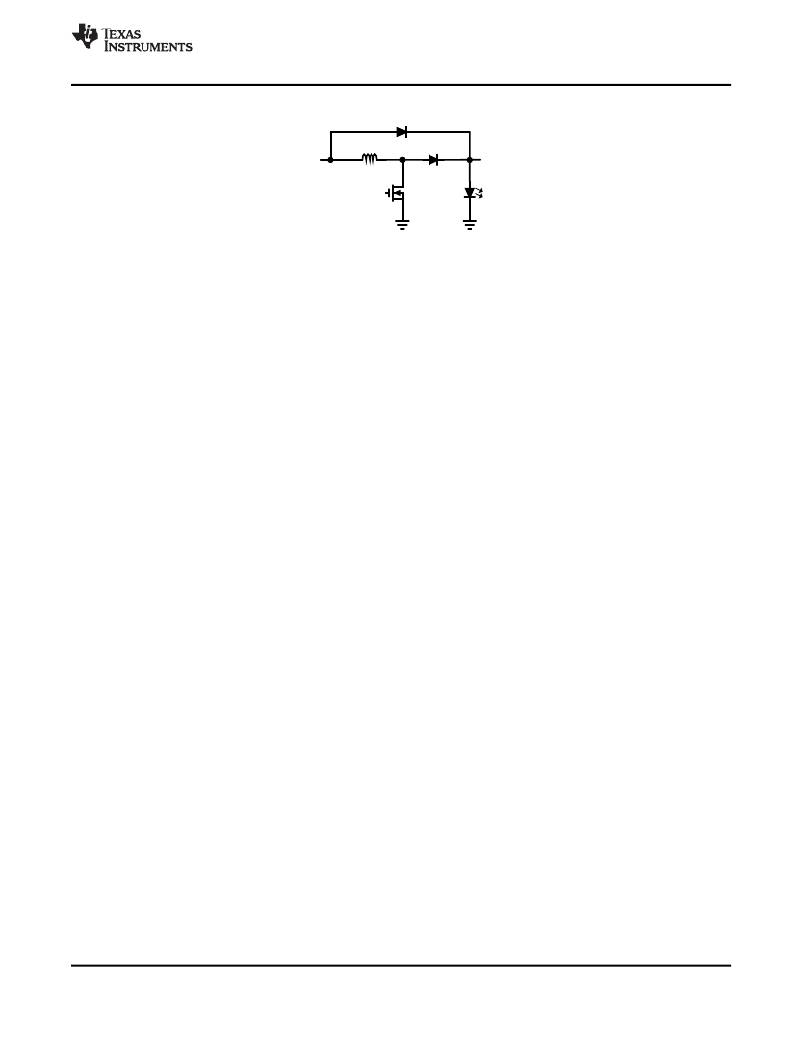
����Boost� Inrush� Diode�
�SNVS574E� –� JULY� 2008� –� REVISED� MAY� 2013�
�V� IN�
�L1�
�D1�
�V� O�
�Q1�
�Figure� 35.� Boost� Topology� with� Inrush� Diode�
�CIRCUIT� LAYOUT�
�The� performance� of� any� switching� regulator� depends� as� much� upon� the� layout� of� the� PCB� as� the� component�
�selection.� Following� a� few� simple� guidelines� will� maximimize� noise� rejection� and� minimize� the� generation� of� EMI�
�within� the� circuit.�
�Discontinuous� currents� are� the� most� likely� to� generate� EMI,� therefore� care� should� be� taken� when� routing� these�
�paths.� The� main� path� for� discontinuous� current� in� the� LM3421/23� buck� regulator� contains� the� input� capacitor�
�(C� IN� ),� the� recirculating� diode� (D1),� the� N-channel� MosFET� (Q1),� and� the� sense� resistor� (R� LIM� ).� In� the� LM3421/23�
�boost� regulator,� the� discontinuous� current� flows� through� the� output� capacitor� (C� O� ),� D1,� Q1,� and� R� LIM� .� In� the� buck-�
�boost� regulator� both� loops� are� discontinuous� and� should� be� carefully� layed� out.� These� loops� should� be� kept� as�
�small� as� possible� and� the� connections� between� all� the� components� should� be� short� and� thick� to� minimize�
�parasitic� inductance.� In� particular,� the� switch� node� (where� L1,� D1� and� Q1� connect)� should� be� just� large� enough�
�to� connect� the� components.� To� minimize� excessive� heating,� large� copper� pours� can� be� placed� adjacent� to� the�
�short� current� path� of� the� switch� node.�
�The� RT,� COMP,� CSH,� IS,� HSP� and� HSN� pins� are� all� high-impedance� inputs� which� couple� external� noise� easily,�
�therefore� the� loops� containing� these� nodes� should� be� minimized� whenever� possible.�
�In� some� applications� the� LED� or� LED� array� can� be� far� away� (several� inches� or� more)� from� the� LM3421/23,� or� on�
�a� separate� PCB� connected� by� a� wiring� harness.� When� an� output� capacitor� is� used� and� the� LED� array� is� large� or�
�separated� from� the� rest� of� the� regulator,� the� output� capacitor� should� be� placed� close� to� the� LEDs� to� reduce� the�
�effects� of� parasitic� inductance� on� the� AC� impedance� of� the� capacitor.�
�Copyright� ?� 2008–2013,� Texas� Instruments� Incorporated�
��27�
�Product� Folder� Links:� LM3421� LM3421-Q1� LM3423� LM3423-Q1�
�发布紧急采购,3分钟左右您将得到回复。
相关PDF资料
LM89EVAL
BOARD EVALUATION LM89
LM95241EB
BOARD EVALUATION LM95241
LOB3R005FLFLT
RES METAL .005 OHM 3W 1% AXIAL
LP05-1A66-80V
RELAY REED SPST 500MA 5V
LP5521TMEV
EVAL BOARD FOR LP5521
LPS0300H1000JB
RESISTOR HEAT SINK 100 OHM 300W
LPS0600H4R70JB
RESISTOR HEAT SINK 4.7 OHM 600W
LPS0800H1000JB
RESISTOR HEAT SINK 100 OHM 800W
相关代理商/技术参数
LM3423MHX
制造商:Rochester Electronics LLC 功能描述: 制造商:Texas Instruments 功能描述:
LM3423MHX/NOPB
功能描述:LED照明驱动器 RoHS:否 制造商:STMicroelectronics 输入电压:11.5 V to 23 V 工作频率: 最大电源电流:1.7 mA 输出电流: 最大工作温度: 安装风格:SMD/SMT 封装 / 箱体:SO-16N
LM3423Q0
制造商:NSC 制造商全称:National Semiconductor 功能描述:N-Channel Controllers for Constant Current LED Drivers
LM3423Q0MH
制造商:NSC 制造商全称:National Semiconductor 功能描述:N-Channel Controllers for Constant Current LED Drivers
LM3423Q0MH/NOPB
功能描述:LED照明驱动器 RoHS:否 制造商:STMicroelectronics 输入电压:11.5 V to 23 V 工作频率: 最大电源电流:1.7 mA 输出电流: 最大工作温度: 安装风格:SMD/SMT 封装 / 箱体:SO-16N
LM3423Q0MHX
制造商:NSC 制造商全称:National Semiconductor 功能描述:N-Channel Controllers for Constant Current LED Drivers
LM3423Q0MHX/NOPB
功能描述:板上安装温度传感器 RoHS:否 制造商:Omron Electronics 输出类型:Digital 配置: 准确性:+/- 1.5 C, +/- 3 C 温度阈值: 数字输出 - 总线接口:2-Wire, I2C, SMBus 电源电压-最大:5.5 V 电源电压-最小:4.5 V 最大工作温度:+ 50 C 最小工作温度:0 C 关闭: 安装风格: 封装 / 箱体: 设备功能:Temperature and Humidity Sensor
LM3423Q1
制造商:NSC 制造商全称:National Semiconductor 功能描述:N-Channel Controllers for Constant Current LED Drivers